|
WARNING!:
IF YOU DO NOT THINK YOU ARE CAPABLE OF DOING ANY OF THESE HOW-TO'S,
HAVE A CERTIFIED MECHANIC DO THE WORK AS I WILL NOT BE LIABLE FOR ANYONE'S MISTAKES MADE DURING ANY OF THESE HOW-TO'S.
You've stumbled upon a great horsepower swap if you've got a base model 88-91 Civic or CRX. If you are not mechanically
able, I wouldn't suggest doing this swap but it is pretty straight forward once you read over how it is done.
Switching from DPFI(Dual Point Fuel Injection) to MPFI(Multi Point Fuel Injection) is basically pretty simple. You are
going from 2 injectors that is almost like simple carbeuration to 4 injectors which is like 4 injectors. Now this
swap is great if you want to spend little money and gain some hidden horsepower.
Here is a list of parts in which I have purchased for the swap to make it easy:
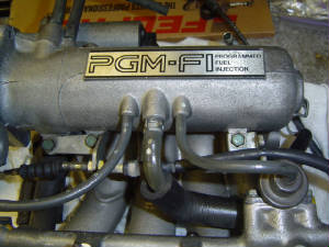
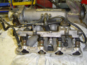
- 88-91 Civic/CRX Si Complete Intake manifold w/Throttlebody and Injectors
- 88-91 Civic/CRX Si Complete Distributor(TD-02U)
- 88-91 Civic/CRX Si Complete Engine Wiring Harness
- 88-91 Civic/CRX Si Injector Resistor Box
- 88-91 Civic/CRX Si PM6 ECU
- 88-91 Civic/CRX Si Throttle Cable
Now most of these parts can be found in the local junkyard or the greatest marketplace in the world, eBay. The engine wiring
harness will make wiring so much easier if you get the complete harness. I say this because it will have all the injector
wiring already there and you wont have to solder so many things together. You'll also have the distributor plug in which you
can pop the pins out of and plug them into the Si plug. More on that later.
Since you will be cutting and soldering wires together, you are going to need some supplies:
- 18 gauge wire 40+ Ft so you have enough
- Automatic Wire Stripper
- Soldering Pen
- Solder
- Heatshrink
- Heat Gun
- Wire Loom 20Ft or so
- Electrical Tape
- Mini Screwdriver(for popping pins)
For the mini screwdriver, you will need to switch some pins on the ecu plugs so this is what I came up that worked
excellent. Basically, Take your mini flathead screwdriver and grind down the one side of it so that the tip will look like
a perfect square. This is so that you can get it to fit in the end of the plugs and be able to butt the blunt end of the screwdriver
on the pin and pop it out. You'll thank me later.
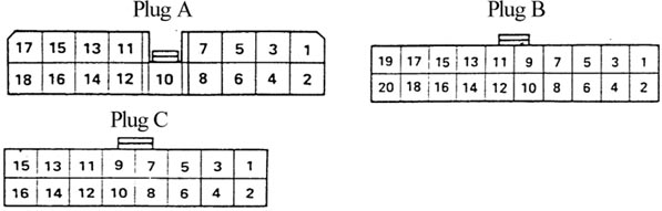
Above is a picture of the ECU Plugs and how you should look at them. Looking at them like that would be the female side
that you would plug into the ecu. Now, There is alot of soldering involve but you'll be glad you soldered all the connections
in the end. I started from the inside of the car with the wiring and worked my way out. Here is how to get started at the
ECU:
Best Method To Do This:
-Pins B10 and B12 are empty meaning there are no wires going into them as
a general rule, however some models have a wire at B12 (if you have one that is one there that is one less wire you will need
to move).
-Pins B2 and B11 have wires going into them but they are not used for anything (weird, but trust me on this one).
-Take the pin/wire from B2, depin it (this means pop it out of the plug) and pin it (pop it into plug) into B10's empty
spot, how you have a wire at B10.
-Take the pin/wire from B11, depin it and clip it into the B12 spot, now you have a wire at B12.
-Cut the orange C1 wire and white C2 wire "in half" (by cut in half I mean cut the wire making sure to leave enough wire
so you can strip and solder them to another wire later). Now when dealing with cutting I will refer to the side of the wire
coming from the interior harness as the harness side, and I will refer to the side of the wire coming directly from the ECU's
plug (direct ECU connection) as the ECU side (the only plug in question for this step is the ones that go into the ECU).
-At the ECU plug, for C1 and C2 solder and heatshrink wires to them and run them into the engine bay (I did this via the
A/C grommets). Mark these wires with a piece of tape saying C1 and C2 on it. Because if you are like me you were using black
wire which all looks the same so you need to make sure you know which is which.
-Now connect and solder the ECU side of B10 onto the harness side of the orange C1 wire, then do the same for the ECU side
of B12 and the harness side of the white C2 wire.
-Cut wires at A3 and A7, solder and heatshrink wires to the plug side of A3 and A7 and run them into the engine bay, make
sure you mark them. Now you should have 4 wires running into your engine bay.
|
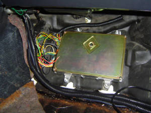
| Location of ECU is under the passenger side footwell. |
|
Wiring Colors and Functions |
|
|
DPFI |
MPFI |
|
Pin # |
Wire Color |
Function |
Wire Color |
Function |
|
A1 |
Yellow 2 |
Aux Injector |
Brown |
#1 Injector |
|
A2 |
Black 1 |
Main Relay/Ground |
Black 1 |
Main Relay/Ground |
|
A3 |
Yellow 1 |
Aux Injector |
Red |
#2 Injector |
|
A4 |
Black 2 |
Main Relay/Ground |
Black 2 |
Main Relay/Ground |
|
A5 |
Red 2 |
Main Injector |
Light Blue |
#3 Injector |
|
A6 |
Green |
Purge Cut Off Solenoid Valve (Coil) |
Green |
Purge Cut Off Solenoid Valve (Coil) |
|
A7 |
Red 1 |
Main Injector |
Yellow 1 |
#4 Injector |
|
A8 |
Yellow 3 |
Sedan LX A/T |
|
|
|
A10 |
Red |
EGR Solenoid Control Valve (Coil) (A/T only) |
|
|
|
A11 |
Blue/Yellow |
EACV (Coil) |
Blue/Yellow |
EACV (Coil) |
|
A12 |
Green/Black 2 |
Main Relay |
Green/Black 2 |
Main Relay |
|
A13 |
Yellow/Black 2 |
Main Relay |
Yellow/Black 2 |
Main Relay/Injector Resistor Box |
|
A14 |
Green/Black 1 |
Main Relay |
Green/Black 1 |
Main Relay |
|
A15 |
Yellow/Black 1 |
Main Relay |
Yellow/Black 1 |
Main Relay/Injector Resistor Box |
|
A16 |
Brown/Black |
Ground |
Brown/Black |
Ground |
|
A17 |
|
|
|
|
|
A18 |
Black/Red |
Ground |
Black/Red |
Ground |
|
|
DPFI |
MPFI |
|
Pin # |
Wire Color |
Function |
Wire Color |
Function |
|
B1 |
White/Green |
Hazard Fuse |
White/Green |
Hazard Fuse |
|
B2 |
Orange |
Tandem Control Solenoid Valve |
Blue 1 |
Fast Idle Control Solenoid Valve |
|
B3 |
Yellow |
A/C Clutch Relay |
Yellow |
A/C Clutch Relay |
|
B4 |
Yellow/Green |
Radiator Fan Relay |
Yellow/Green |
Radiator Fan Relay |
|
B5 |
White/Yellow |
Alternator |
White/Yellow |
Alternator |
|
B6 |
Green/Orange |
Check Engine Warning Light |
Green/Orange |
Check Engine Warning Light |
|
B7 |
Green/Orange |
A/T Shift Position Console Switch (Park, Neutral) |
|
|
|
B8 |
Blue/Red |
A/C Switch |
Blue/Red |
A/C Switch |
|
B9 |
|
|
|
|
|
B10 |
|
|
Orange |
Crank Angle Sensor |
|
B11 |
Green/Black |
A/T Shift Position Console Switch (Drive) |
|
|
|
B12 |
|
|
White |
Crank Angle Sensor |
|
B13 |
Blue White |
Main Relay |
Blue White |
Main Relay |
|
B14 |
Blue 2 |
To Yellow, To Alternator |
Blue 2 |
Alternator |
|
B15 |
White 1 |
Ignitor Unit |
White 1 |
Ignitor Unit |
|
B16 |
Yellow/Red |
Speed Sensor |
Yellow/Red |
Speed Sensor |
|
B17 |
White 2 |
Ignitor Unit |
White 2 |
Ignitor Unit |
|
B18 |
|
|
|
|
|
B19 |
Green/Red |
Electric Load Detector |
Green/Red |
Electric Load Detector |
|
B20 |
Brown |
Ignition Timing Adjusting Connector |
Brown |
Ignition Timing Adjusting Connector |
|
|
DPFI |
MPFI |
|
Pin # |
Wire Color |
Function |
Wire Color |
Function |
|
C1 |
Orange |
Crank Angle Sensor |
Blue/Green |
Cylinder Position Sensor |
|
C2 |
White 4 |
Crank Angle Sensor |
Blue/Yellow |
Cylinder Position Sensor |
|
C3 |
Orange/Blue |
TDC Sensor |
Orange/Blue |
TDC Sensor |
|
C4 |
White/Blue |
TDC Sensor |
White/Blue |
TDC Sensor |
|
C5 |
Red/Yellow |
TA Sensor |
Red/Yellow |
TA Sensor |
|
C6 |
Red/White 1 |
TW Sensor |
Red/White 1 |
TW Sensor |
|
C7 |
Red/Blue |
Throttle (Position) Angle Sensor (TPS) |
Red/Blue |
Throttle (Position) Angle Sensor (TPS) |
|
C8 |
Yellow |
EGR Lift Valve Sensor |
|
|
|
C9 |
Red/White 2 |
PA Sensor |
Red/White 2 |
PA Sensor |
|
C10 |
Green/White 3 |
Brake Switch |
Green/White 3 |
Brake Switch |
|
C11 |
White 1 |
MAP Sensor |
White 1 |
MAP Sensor |
|
C12 |
Green/White 2 |
EGR Lift Valve Sensor/Pa Sensor/Ignition Timing Adjusting Connector/TA Sensor/TPS Sensor/TW Sensor |
Green White 2 |
Pa Sensor/Ignition Timing Adjusting Connector/TA Sensor/TPS Sensor/TW Sensor |
|
C13 |
Yellow/White |
EGR Lift Valve Sensor/Pa Sensor/TPS Sensor |
Yellow/White |
Pa Sensor/TPS Sensor |
|
C14 |
Green/White 1 |
MAP Sensor |
Green/White 1 |
MAP Sensor |
|
C15 |
Yellow/Red |
MAP Sensor |
Yellow/Red |
MAP Sensor |
|
C16 |
White 3 |
O2 Sensor |
White 3 |
O2 Sensor |
|
|
Next, you're going to want to move into the engine bay. If you can find a plug from a junkyard with 4 wires coming out
of it, it will help you out in the long run if you ever swap your old motor for something else. Adding a plug after the firewall
will allow you to easily unplug your new wiring quickly. After you have the plug wired up and you have soldered lengths
of wire onto them, you can start with some easier of the wiring.
-Throttle Position Sensor (TPS) wires need to be extended, the TPS is a black sensor on the side of the throttle body,
there are 3 wires going to it, extend those, always solder and use heatshrink. On the TPS plug on the DX harness you will
see 3 wires going to it, yellow, red, and green, in that order (if you are looking at the top of the clip from left to right
on the DX clip). Depin and switch the green and yellow wires around so now the order is green, red, yellow. This is because
the DX TPS sensor works in the reverse of the MPFI one, so if you didn't do that your car would think it was at redline when
it was suppose to be at idle. So if you have that problem you know you skipped this step.
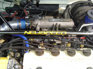
-Electronic Air Control Valve (EACV) wires need to be extended, the EACV is a rectangular box on the back of the intake
manifold, it has 2 wires going to it, solder and heatshrink.
Next, you can mount the injector resistor box on the driver's side in between the firewall and the strut tower. There
is already a 10mm bolt there that you can just mount it to.
Now you can start with the rest of the wiring and this is where you will thank me for getting the entire Si wiring harness.
You can't plug the Si wiring harness in to the DX harness, if you're wondering, it just doesn't work. But you will chop up
about half of the harness to get what you need off of it.
-The DX has 2 injector plugs on it, cut them off as close to the plug as you can. Connect all the yellow/black wires from
those injector plug wires and solder them all together. From that combined connection solder on another wire and run it to
the yellow/black wire on the Injector Resistor Box.
-Connect the solid yellow wire from the DX injector to the #1 injector (I insert all the signal wires onto the left side
of the injector plug, and all the resistor box wires on the right side, though I'm not sure it matters).
-Connect the solid red wire from the DX injector and run it to the #3 injector (onto the left side of the plug, like I
mentioned above).
-Connect the A3 wire to the #2 injector (left side).
-Connect the A7 wire to the #4 injector (left side).
-Now run a wire from the right side of each injector plug and connect it to the red/black wires on the injector resistor
box (the order doesn't matter from what I've seen).
If you read the instructions carefully, technically you wouldn't need to run a wire from each right side of the injector
plug if you have the whole harness intact. Leave the injector wiring from main part of the harness intact but take all the
looming and tape off so you can get at the wiring and you'll know what I mean. All you would need to do is splice into
the left side of the wires with A3, A7, and the wires from the DX Injectors. It cuts down on the soldering.
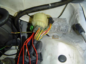
In the picture above is the injector resistor box. It is kind of difficult to see the green plug but that is the plug hiding
under the big white plug.
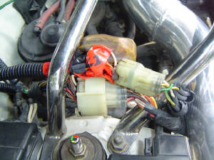
The last thing you really need to do is wire the Cylinder position sensor and its pretty easy. From the Si harness, snip
the other half of the distributor plug with the 6 or 7 wires coming out of it. Then match up the wires between the two plugs
and you are good to go.
-Connect the C1 wire to the blue/green wire on the CPS (the sensor is inside the Distributor on a SOHC engine). For doing
this I suggest swapping out to the proper Si distributor plug so it is all plug and play and looks clean.
-Connect the
C2 wire to the blue/yellow wire on the CPS.
|